FINALLY!
I finally have the toner transfer method for single sided boards down! The important thing is to use PHOTO PAPER... I was trying to get away with standard printer/copier paper...
 I used HP Everyday Photo Paper, on an HP LaserJet 1012 printer. 25 sheets cost me R75, so R3 a shot. Let me explain why you need to use photo paper instead of normal paper... Toner is plastic particles... that get burned on to the paper by the laser in the laser printer. On the normal paper the plastic toner particles get infused with the paper fiber & then they dont seperate properly in water... maybe if I left a board in water over night normal paper could work...? (I'm not really patient enough to find out...) With photo paper... & if you look click the packaging phtoto to enlarge it, you will see it is SEMI-GLOSSY... I think this means that there is only 1 glossy side... which is perfect for me... the glossy side is glossy enough... so the toner gets burned onto the thin plastic layer of gloss on the phtoto paper... which allows for this... :)
 The paper layer magically seperates from the thin plastic layer! I just pulled one corner of the paper & it all came off at once together!
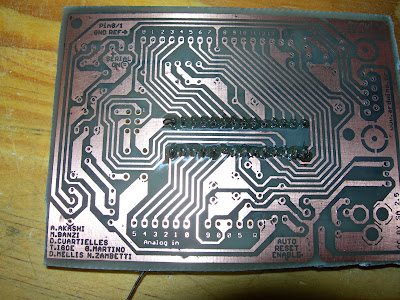
 I rubbed the rest of the paper residue off with my thumb, took the board out & dried it... it looked like this! What you see is a thin layer of burned gloss! so I...
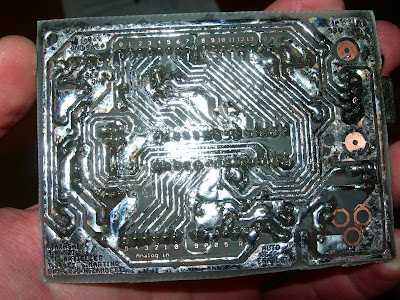
 Re submerged the board in the water, got an old tooth brush & scrubbed that all off... scrubed pretty heard... the toner was firmly attached to the copper.
 & the finished result :) pretty much perfect... there were two tracks that had a small gap in them...
 It was a hot day, not a cloud in the sky, probably 35 degrees Celsius! I heard the ferric chloride reaction works better the warmer it is & in direct sun light... which it did. I used another tooth brush to rub the copper. It was a much faster reaction! Probably under 10 minutes... & yes! I am fed up with the smell of ferric chloride & the fumes that it releases. I decided to use the protective equipment I have! Because I was using a tooth brush in the ferric chloride, some ferric chloride sprinkled its self onto my cloths :(
 This is the result after rinsing in water. I'm told another way to speed up the reaction is to put a second paint tray with boiling water under the paint tray with ferric chloride! This also work, I made a stepper driver this weekend using the hot water in the bottom paint tray, it was a cloudy day that day... the reaction was very quick, also around 10minutes or less!
 Left: the new PCB etched, Right: an older PCP.
 I left the toner on, so I could identify where to drill the holes a bit easier... I think all the holes, pads & via's should be 1mm! getting hold of 0.7mm, 0.8mm was difficult... I couldn't find any 0.9mm bits! My drill press is still on its way! I used a drill press for the first stepper board! A drill press makes a 1hr40min job complete in 20 minutes! I am seriously considering trying a board with an SMD component! since I have my toner transfer method working well... I dont want to WASTE time drilling holes!
 I placed all the components on the board just to make sure all the holes were drilled & that everything could fit where it was supposed to. I have 5mm LED's, but now see that i need 3mm LED's instead.
 View from the side.
 View from under.
 I decided to put the top ink on!
 I didn't align it 100% but it was good enough, also I didnt let the paper soak in water long enough so some markings stayed on the paper...
 I then cleaned the toner off with thinners & soldered the most exciting componet first... I now realize that the smallest components should be first... resistors...
 capacitors & the choke
 I started tinning as I went along. I now know a better technique! Tin the whole board first, then put in the components!
 resistors & diodes...
 tin
tin
 tin for more components. my soldering iron's thermostat was still broken at this time so the tracks started lifting off the fiber glass :(
 Finished top view
 Finished bottom view.
I read somewhere that opaque transparencies can be used... when you iron the PCB layout onto the coper, just the toner moves off the transparency then you submurge in cold water & the plactic transparency just seperates from the copper, leaving the toner on the copper & then you can reuse the transparency :) I might trie this...
so im waiting for my soldering iron to come back from repair before make another arduino, & then make some stepper motor dirver boards!
 I used HP Everyday Photo Paper, on an HP LaserJet 1012 printer. 25 sheets cost me R75, so R3 a shot. Let me explain why you need to use photo paper instead of normal paper... Toner is plastic particles... that get burned on to the paper by the laser in the laser printer. On the normal paper the plastic toner particles get infused with the paper fiber & then they dont seperate properly in water... maybe if I left a board in water over night normal paper could work...? (I'm not really patient enough to find out...) With photo paper... & if you look click the packaging phtoto to enlarge it, you will see it is SEMI-GLOSSY... I think this means that there is only 1 glossy side... which is perfect for me... the glossy side is glossy enough... so the toner gets burned onto the thin plastic layer of gloss on the phtoto paper... which allows for this... :)
 The paper layer magically seperates from the thin plastic layer! I just pulled one corner of the paper & it all came off at once together!
 I rubbed the rest of the paper residue off with my thumb, took the board out & dried it... it looked like this! What you see is a thin layer of burned gloss! so I...
 Re submerged the board in the water, got an old tooth brush & scrubbed that all off... scrubed pretty heard... the toner was firmly attached to the copper.
 & the finished result :) pretty much perfect... there were two tracks that had a small gap in them...
 It was a hot day, not a cloud in the sky, probably 35 degrees Celsius! I heard the ferric chloride reaction works better the warmer it is & in direct sun light... which it did. I used another tooth brush to rub the copper. It was a much faster reaction! Probably under 10 minutes... & yes! I am fed up with the smell of ferric chloride & the fumes that it releases. I decided to use the protective equipment I have! Because I was using a tooth brush in the ferric chloride, some ferric chloride sprinkled its self onto my cloths :(
 This is the result after rinsing in water. I'm told another way to speed up the reaction is to put a second paint tray with boiling water under the paint tray with ferric chloride! This also work, I made a stepper driver this weekend using the hot water in the bottom paint tray, it was a cloudy day that day... the reaction was very quick, also around 10minutes or less!
 Left: the new PCB etched, Right: an older PCP.
 I left the toner on, so I could identify where to drill the holes a bit easier... I think all the holes, pads & via's should be 1mm! getting hold of 0.7mm, 0.8mm was difficult... I couldn't find any 0.9mm bits! My drill press is still on its way! I used a drill press for the first stepper board! A drill press makes a 1hr40min job complete in 20 minutes! I am seriously considering trying a board with an SMD component! since I have my toner transfer method working well... I dont want to WASTE time drilling holes!
 I placed all the components on the board just to make sure all the holes were drilled & that everything could fit where it was supposed to. I have 5mm LED's, but now see that i need 3mm LED's instead.
 View from the side.
 View from under.
 I decided to put the top ink on!
 I didn't align it 100% but it was good enough, also I didnt let the paper soak in water long enough so some markings stayed on the paper...
 I then cleaned the toner off with thinners & soldered the most exciting componet first... I now realize that the smallest components should be first... resistors...
 capacitors & the choke
 I started tinning as I went along. I now know a better technique! Tin the whole board first, then put in the components!
 resistors & diodes...
 tin
tin tin for more components. my soldering iron's thermostat was still broken at this time so the tracks started lifting off the fiber glass :(
 Finished top view
 Finished bottom view.
I read somewhere that opaque transparencies can be used... when you iron the PCB layout onto the coper, just the toner moves off the transparency then you submurge in cold water & the plactic transparency just seperates from the copper, leaving the toner on the copper & then you can reuse the transparency :) I might trie this...
so im waiting for my soldering iron to come back from repair before make another arduino, & then make some stepper motor dirver boards!