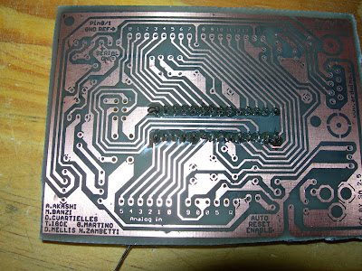
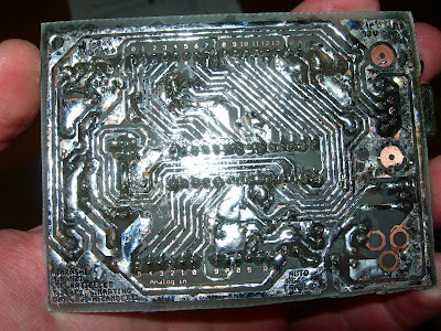
Showing posts with label Arduino. Show all posts

Thursday, October 8, 2009

Wiring up - Round 1

last night, (as in the date on the photos... I'm re posting this from my back up blog site...) I finally took the time to work on my repstrap again… when I say TOOK the time… look at the time on the photos… all in all I spent 4hours working on the robot.

This is what I did:

  1. I placed all the boards on the perspex, and drilled holls for them… making good use of my drill press :) no photos of that needed.
  2. Starting with the arduino and shield, I put :: M3×50 machine screws > washer > PCB > clear tubing > perspex > washer > nut.

  3. Here is the arduino mounted

  4. Here are the 3 stepper driver boards mounted with the arduino showing. This is a view from behind.

  5. Here are all the boards mounted, the two new additions are the PWM driver & the DC motor driver.

  6. And now my wiring nightmares begin… Just take a look at this rats nest! what a mess…

  7. Next I mounted the perspex to the Z axis of the rep strap. The Z axis was taken off to make this a bit easier…

  8. Here is a close up of the clear tubing. Its purpose is to act as a “shock absorber” for bumps and also so that the perspex does not crack if I tighten the screws too tight… which I do… The clear tubing was used to attach all PCB’s
    Because the rats nest is such a mess, I am now going to have to de-solder the IDL headers and hard wire cat 5e cable in its place, this will make it easier to connect to the arduino break away shield and easier to route the wires.

Monday, February 2, 2009

SUCCESS: Toner trasfer 3rd try

FINALLY!

I finally have the toner transfer method for single sided boards down! The important thing is to use PHOTO PAPER... I was trying to get away with standard printer/copier paper...
I used HP Everyday Photo Paper, on an HP LaserJet 1012 printer. 25 sheets cost me R75, so R3 a shot. Let me explain why you need to use photo paper instead of normal paper... Toner is plastic particles... that get burned on to the paper by the laser in the laser printer. On the normal paper the plastic toner particles get infused with the paper fiber & then they dont seperate properly in water... maybe if I left a board in water over night normal paper could work...? (I'm not really patient enough to find out...) With photo paper... & if you look click the packaging phtoto to enlarge it, you will see it is SEMI-GLOSSY... I think this means that there is only 1 glossy side... which is perfect for me... the glossy side is glossy enough... so the toner gets burned onto the thin plastic layer of gloss on the phtoto paper... which allows for this... :)
The paper layer magically seperates from the thin plastic layer! I just pulled one corner of the paper & it all came off at once together!
I rubbed the rest of the paper residue off with my thumb, took the board out & dried it... it looked like this! What you see is a thin layer of burned gloss! so I...
Re submerged the board in the water, got an old tooth brush & scrubbed that all off... scrubed pretty heard... the toner was firmly attached to the copper.
& the finished result :) pretty much perfect... there were two tracks that had a small gap in them...
It was a hot day, not a cloud in the sky, probably 35 degrees Celsius! I heard the ferric chloride reaction works better the warmer it is & in direct sun light... which it did. I used another tooth brush to rub the copper. It was a much faster reaction! Probably under 10 minutes... & yes! I am fed up with the smell of ferric chloride & the fumes that it releases. I decided to use the protective equipment I have! Because I was using a tooth brush in the ferric chloride, some ferric chloride sprinkled its self onto my cloths :(
This is the result after rinsing in water. I'm told another way to speed up the reaction is to put a second paint tray with boiling water under the paint tray with ferric chloride! This also work, I made a stepper driver this weekend using the hot water in the bottom paint tray, it was a cloudy day that day... the reaction was very quick, also around 10minutes or less!
Left: the new PCB etched, Right: an older PCP.
I left the toner on, so I could identify where to drill the holes a bit easier... I think all the holes, pads & via's should be 1mm! getting hold of 0.7mm, 0.8mm was difficult... I couldn't find any 0.9mm bits! My drill press is still on its way! I used a drill press for the first stepper board! A drill press makes a 1hr40min job complete in 20 minutes! I am seriously considering trying a board with an SMD component! since I have my toner transfer method working well... I dont want to WASTE time drilling holes!
I placed all the components on the board just to make sure all the holes were drilled & that everything could fit where it was supposed to. I have 5mm LED's, but now see that i need 3mm LED's instead.
View from the side.
View from under.
I decided to put the top ink on!
I didn't align it 100% but it was good enough, also I didnt let the paper soak in water long enough so some markings stayed on the paper...
I then cleaned the toner off with thinners & soldered the most exciting componet first... I now realize that the smallest components should be first... resistors...
capacitors & the choke
I started tinning as I went along. I now know a better technique! Tin the whole board first, then put in the components!
resistors & diodes...
tin
tin for more components. my soldering iron's thermostat was still broken at this time so the tracks started lifting off the fiber glass :(
Finished top view
Finished bottom view.

I read somewhere that opaque transparencies can be used... when you iron the PCB layout onto the coper, just the toner moves off the transparency then you submurge in cold water & the plactic transparency just seperates from the copper, leaving the toner on the copper & then you can reuse the transparency :) I might trie this...

so im waiting for my soldering iron to come back from repair before make another arduino, & then make some stepper motor dirver boards!

Tuesday, January 13, 2009

FAILED: Toner trasfer 2nd try

I am so close to getting this right now... but not quite yet.

Clean a piece of copper board with thinners & some mutton cloth or a rag.
Use scotch bright bad to clean the copper to a shine. The scotch bright pad is very abrasive & leaves a thin layer of copper partials all over the board. You wont be able to see them but wiping the board down again with some cloth will show... I know this because i tried *this* method of toner transfer & the transfer was patchy... I rinsed the board in water, then wiped it down again.
Turn you iron onto the hottest setting. It's probably better to use a NON-STEAM IRON, but mine was a steam iron, so I had to drain out all the water first.
Print the positive mirror of the board you want. Use the highest print settings. I used standard copy paper & a laser printer.
Use masking tape to tape on end of the print out to the board, then stretch the other end & tape it. Tape everything so that it is tight. this ensures that there will be no air bubbles in the paper when you iron it.
Center the iron over the board, & leave it there for 2 minutes.
Use your 2 minutes to fill up the kettle & boil the water.
Iron the board in every direction putting pressure. You can stop ironing once you hear the kettle has boiled.
So after a total of 5 minutes of ironing my board looked like this. I left it to cool for a bit while I...
Plugged up the kitchen sink & emptied the kettle into the sink.
Let is sit in the boiling water for about 13 minutes, you should be able to see the tracks through the paper.
Rub the paper with your finger. the paper should easily dissolve & come off.
  1. Don't rub in the same spot for too long. The toner tracks will break.
  2. Don't rub too hard. The toner tracks will break.
  3. Don't rub too fast. The toner tracks will break.
  4. Once there as some paper balls, shake them off so that the don't roll over the board again. If you don't, the toner tracks will break.
Here you can see the paper balls forming.
After all the paper is off, this is what the board looks like. Some of the tracks were damaged, so...
I tried my best to touch them up with a permanent marker, but the tip was to fat!
pore half a bottle of ferric chloride in a paint tray.
Submerge the board in ferric chloride. This photo angle shows there was still some paper residue on the board!
I wish i had a shake table! The fumes were so strong! I sat there for 45 minutes shacking the paint tray to agitate the solution in the hope that the reaction would go faster. I Did this for 25 minutes which was not enough. so then I checked on a 5 minutes interval.
Put on a glove & rinse the board in a separate paint tray containing tap water.
Once my board looked like this I decided it was done etching. In some places it was over exposed & the copper tracks were eaten away. Dry the board with a paper towel.
Pour the ferric chloride back in the container. The solution becomes weaker but that's ok. When this solution begins to take too long to do reactions I will try the pool acid & hydrogen peroxide! At least that is clear. (so you can see the reaction happening)
Take some thinners & a cloth & wipe off the toner, leaving the developed PCB. As you can see from this picture there are broken tracks everywhere. The next day, the board looked like it was oxidizing again. I should probably mention it has been raining a lot lately & there is a lot of moisture in the air.

So if anyone has read this & has a working method for toner transfer PCB etching & wants to save me some trouble, please let me know! Photos of each step would be really nice, but at this point I would settle for very explicit, clear & unambiguous instructions.

And Yes, I am aware that the exposure time for the board in the acid depends on:
  1. the size of the board
  2. the amount of exposed copper that needs to react
  3. the strength of the acid
  4. the temperature of the acid - (there is no ways I will heat up any acid! That's where i draw the line)
This is painful!